
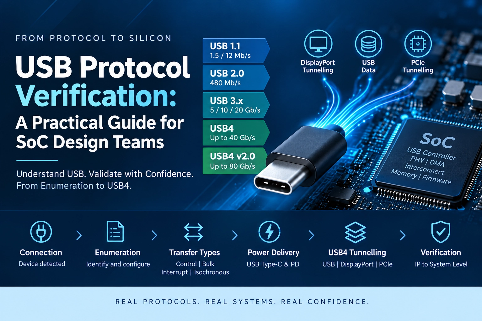
USB protocol verification means checking that a USB controller, its PHY, and the software around it behave correctly at every layer of the USB stack: enumeration, the four transfer types, power negotiation, and, for USB4, protocol tunnelling, before a chip goes anywhere near silicon. USB is one of the richest interfaces a verification engineer will ever test, because a single storage read touches the connector, the controller, DMA, the on-chip interconnect, memory, and firmware in one pass. This guide walks through how USB actually works, from the first USB 1.1 peripherals to USB4 Version 2.0, and points out where each part of the protocol turns into a real test case inside a UVM environment.
USB Is a Protocol Family, Not a Connector
USB started as a way to replace a shelf full of mismatched PC connectors: serial ports, parallel ports, PS/2 ports, and several proprietary interfaces that each needed their own driver model and setup process. What USB actually delivered was bigger than a single connector: a full set of specifications defining how devices connect, how data moves, how a device tells the system what it is, and how power gets delivered alongside data.
The simplest way to picture it: USB is a conversation between a Host and a Device. The Host finds the Device, learns what it is, picks a configuration, and then exchanges data through endpoints. Everything else in this guide is a variation on that basic pattern.
USB Generations: From USB 1.1 to USB4 Version 2.0
USB has gone through several generations, and the naming has not always kept pace with the underlying technology. The table below lays out the nominal signalling speed for each generation.
| Generation | Main idea | Nominal signalling / data capability |
| USB 1.0 / 1.1 | Simple universal peripheral bus | Low-Speed 1.5 Mb/s; Full-Speed 12 Mb/s |
| USB 2.0 | Faster, general-purpose USB | High-Speed 480 Mb/s |
| USB 3.0 | SuperSpeed introduced | 5 Gb/s |
| USB 3.1 / 3.2 | Higher SuperSpeed generations | 5, 10, or 20 Gb/s depending on generation and lane configuration |
| USB4 | High-speed transport with tunnelling | Up to 40 Gb/s |
| USB4 Version 2.0 | Extended transport framework | Up to 80 Gb/s |
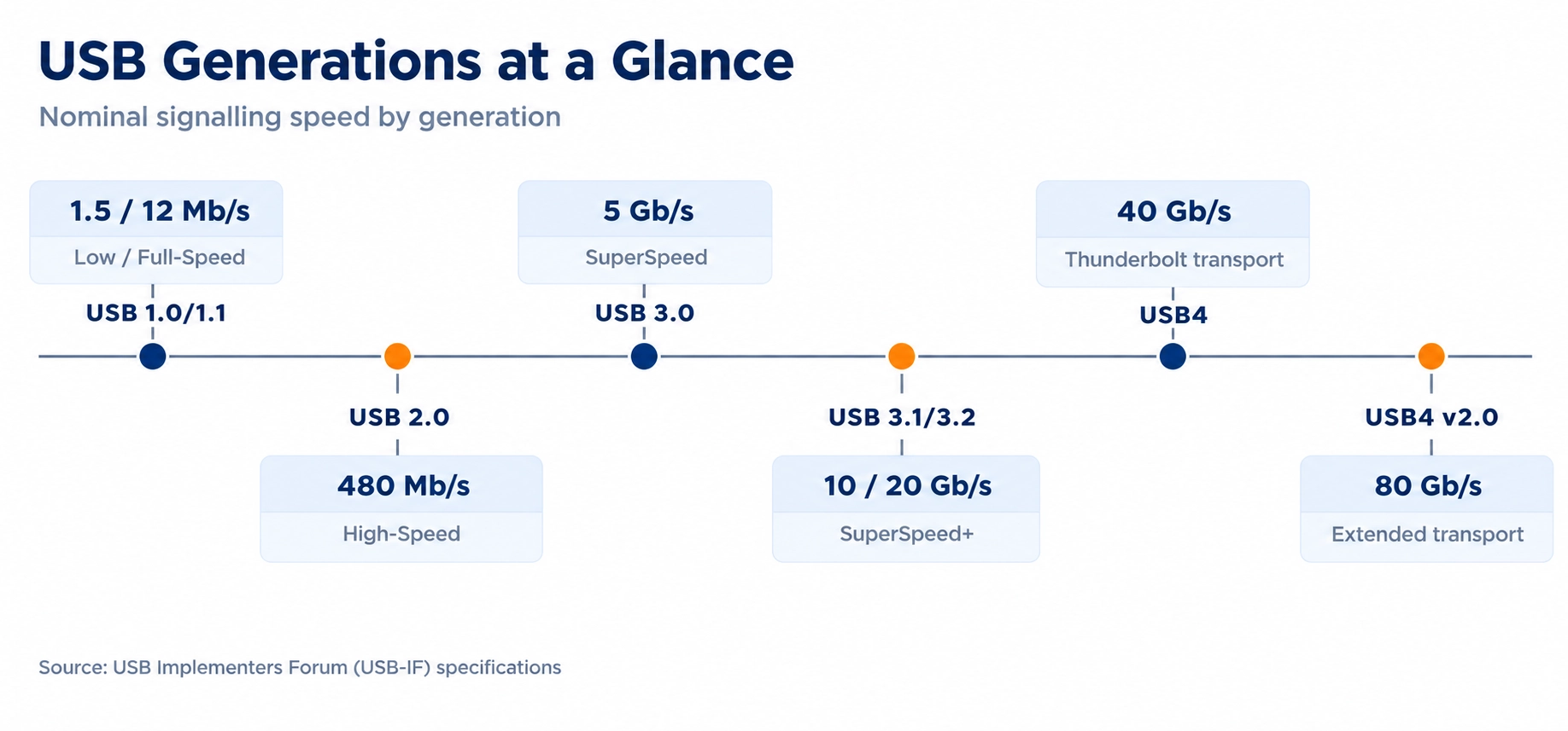
A naming lesson worth remembering. The marketing name, the connector type, and the actual speed a product delivers are three different things. USB Type-C describes a connector and cable interface. It says nothing on its own about whether a port supports USB 3.x or USB4. Before assuming what a port can do, ask three questions: what connector does it use, what USB generation does it support, and what speed and features are actually negotiated when a device is plugged in?
USB-IF later folded earlier SuperSpeed branding into the USB 3.2 specification, which is why an older product box might say USB 3.0 or USB 3.1 while newer technical documentation describes the same silicon using USB 3.2 generation terminology. A team scoping USB verification work through a VLSI design partner needs to confirm which generation is actually implemented in RTL, not which name appears on the datasheet cover.
USB Architecture: Host, Hub, Device, Endpoint, Pipe
At the top level, a USB system has a Host and one or more Devices, and Hubs let the topology expand to support more of them.
| Component | Plain meaning |
| Host | Controls the bus and starts USB transactions |
| Device | Peripheral connected to the Host |
| Hub | Expands the USB topology and connects downstream devices |
| Endpoint | Logical source or destination of data inside a USB device |
| Pipe | Logical communication path between Host software and an endpoint |
| Interface | Group of endpoints that provides one function |
| Configuration | A selected set of interfaces for a device |
A CI/CD pipeline example, start to finish
Take a payments team fixing a rounding bug in a currency conversion function.
A developer writes the fix and a unit test that fails without it. They push the branch and open a pull request. The pipeline starts within seconds.
Linting and static analysis run first and finish in under a minute. The build compiles the service and produces a container image tagged with the commit hash. Unit tests run in ninety seconds and pass, including the new one. Integration tests spin up a test database and a mock payment provider, run for four minutes, and pass. Dependency scanning finds nothing new.
Total elapsed time: about eight minutes. The pull request shows green. A colleague reviews the change, approves it, and merges.
The merge triggers the main pipeline. The same checks run again, plus the end-to-end suite, which takes eleven minutes. The image is pushed to the registry and deployed to staging. Smoke tests confirm the service starts, answers health checks and converts a sample transaction correctly.
Under continuous delivery, the change now waits. A release manager sends it live during the afternoon window. Under continuous deployment, it goes to production on its own, canary first, at five percent of traffic for ten minutes while error rates are watched, then to everyone.
From commit to production: under an hour, most of it automated.
The same fix in a team without a pipeline looks different. The developer tests locally and merges. The change sits in main with eleven others until the fortnightly release. Someone builds a release candidate by hand, deploys it to a shared test environment, and finds that two of the twelve changes conflict. Working out which two takes a day. The release slips a week. When it finally ships, twelve changes go live together, and the incident that follows takes three hours to trace back to the rounding fix.
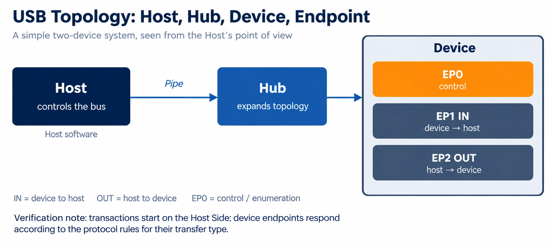
A real USB device is often more than one function wrapped in a single connector. A composite device, say a keyboard with a built-in trackpad, can expose a keyboard interface and a pointing-device interface at the same time, each with its own endpoints.
Endpoint direction is worth memorising early: OUT means data travels from Host to Device, IN means data travels from Device to Host, and endpoint 0 is reserved for control transfers and enumeration. A simple system looks like Host to Hub to Device, and the point that matters for test planning is that transactions originate on the Host side, while device endpoints respond according to the rules for their transfer type.
How a USB Device Comes Alive: The Enumeration Process
Enumeration is one of the most important ideas in USB, and it is also where a large share of protocol bugs hide. When a device is plugged in, the Host has no idea whether it is a keyboard, a storage drive, or a camera. It has to find out step by step:
- The physical connection is detected.
- The Host resets the USB device.
- The device receives a default address.
- The Host requests descriptors.
- The Host reads device, configuration, and interface information.
- The Host assigns a unique USB address.
- The Host selects a configuration.
- Normal application transfers can begin.
Descriptors are the device’s identity card. They are structured data blocks that tell the Host what a device is and how it is organised. The main descriptor types are Device, Configuration, Interface, Endpoint, and String descriptors, and getting any one of them wrong can stall enumeration entirely.
Enumeration exercises reset behaviour, control transfers, descriptor correctness, address handling, endpoint configuration, and a long list of edge cases: timeouts, malformed descriptors, unexpected disconnects mid-sequence. A verification plan that treats enumeration as a boring setup step before the “real” testing begins is missing one of the largest functional areas in the whole protocol. It is also one of the first things a DV engineer building a USB testbench should stress deliberately, well beyond the happy-path sequence.
The Four USB Transfer Types Explained
USB defines four transfer types because a keyboard, a disk, and an audio stream have very different traffic patterns, and none of them would be served well by a single generic transfer model.
| Transfer type | Main purpose | Typical characteristic |
| Control | Commands, setup, configuration | Reliable control communication |
| Bulk | Large data such as storage | Reliable, uses bandwidth when available |
| Interrupt | Small, periodic, or event-driven data | Bounded service opportunity, used for HID-style devices |
| Isochronous | Audio and video streams | Time-sensitive delivery designed for streaming |
A common misconception. “Interrupt transfer” does not mean a device can electrically interrupt the Host whenever it wants. USB is Host-controlled from end to end: the Host schedules bus activity and offers each device a service opportunity; it does not hand control to the device on demand.
A quick way to hold the four types in memory: Control configures, Bulk moves reliable data, Interrupt handles small periodic or event data, and Isochronous carries a continuous, time-sensitive stream. From a test-planning point of view, a solid verification plan generates traffic for every supported transfer type, varies packet sizes, pushes against boundaries, runs back-to-back transactions, injects protocol errors where the spec allows for them, and checks both data correctness and protocol compliance, not just one of the two.
USB 2.0 versus USB 3.x SuperSpeed: What Changed
USB 1.1 introduced the basic universal bus idea and became the widely used early implementation, supporting Low-Speed and Full-Speed operation. USB 2.0 then added High-Speed operation at 480 Mb/s while keeping backward compatibility with the earlier speeds. That was a large step up, because USB could now carry far more demanding peripherals.
| Mode | Nominal signalling rate |
| Low-Speed | 1.5 Mb/s |
| Full-Speed | 12 Mb/s |
| High-Speed | 480 Mb/s |
USB 3.0 introduced the SuperSpeed architecture, and compared with USB 2.0 the high-speed data path became far more capable, with new protocol behaviour and signalling to match.
| Common USB 3.x label | Nominal capability |
| USB 3.2 Gen 1 | 5 Gb/s |
| USB 3.2 Gen 2 | 10 Gb/s |
| USB 3.2 Gen 2×2 | 20 Gb/s |
USB 2.0 has not disappeared now that SuperSpeed and USB4 exist. It remains widely used for compatibility, low-cost devices, embedded functions, and the USB 2.0 data path that still runs alongside newer capability inside many Type-C systems. A modern connector does not guarantee a modern protocol underneath it. At SuperSpeed, test focus moves beyond checking payload bytes: link behaviour, ordered protocol events, flow control, packet sequencing, error handling, and state transitions all become areas that need dedicated coverage.
USB Type-C and USB Power Delivery Are Not the Same Thing
USB Type-C changed the physical experience of using USB. The connector is reversible, compact, and built to support several capabilities at once. But the single most important rule to hold onto is that Type-C is a connector specification, not a guarantee of USB 3.x, USB4, or USB Power Delivery.
USB Power Delivery (USB PD) is a separate protocol for negotiating power between connected devices, letting a source and a sink agree on what power can be supplied or requested. Data capability, the Type-C connector, and USB PD are related but distinct:
- USB data capability comes from the USB protocol and physical paths a product actually supports.
- Type-C defines the connector and the electrical and mechanical ecosystem around it.
- USB PD defines power negotiation and delivery behaviour.
- A product can support one of these without supporting all the others.
This distinction matters directly in SoC verification. A Type-C controller can involve orientation detection, role management, USB data paths, PD messaging, power-state control, alternate modes, and interrupt or status reporting, often built alongside the rest of an embedded systems block. A subsystem-level testbench has to check these pieces together. One register write at a time is not enough to catch how they interact.
USB4: When USB Became a Transport
USB4 extends USB beyond carrying traditional USB transactions on its own. It is a high-speed transport architecture capable of tunnelling several protocols across one physical link:
- USB data
- DisplayPort traffic
- PCI Express tunnelling, on supported systems
- Other protocol traffic carried through the USB4 architecture
Instead of building a separate high-speed link for every function a platform needs, USB4 lets one high-speed connection carry several traffic types at once. USB4 began with up to 40 Gb/s, and USB4 Version 2.0 extended the framework to support up to 80 Gb/s, along with further updates to tunnelling and protocol support.
A useful mental picture: think of USB4 as a shared highway. USB data, display traffic, and other supported protocols are different vehicles, and the transport system manages how those flows share the road. That sharing is exactly what makes verification harder: a USB4 environment has to account for transport behaviour, protocol tunnelling, arbitration and resource sharing, link states, error handling, and end-to-end data correctness, on top of everything a USB 3.x environment already checks.
Where USB Lives Inside a Real SoC
The connector is only the outside world. Inside a real SoC, several blocks cooperate to make a single USB transaction work.
| Block | Typical responsibility |
| USB PHY | Electrical and physical layer interface |
| USB Controller | Protocol, link, and transaction handling |
| Endpoint logic | Buffers and manages endpoint data |
| DMA | Moves large data between USB and memory |
| AXI / NoC interconnect | Carries internal SoC transactions |
| Memory controller | Connects the system to DDR or other memory |
| Interrupt controller | Reports events to the CPU |
| CPU / Firmware | Configures and controls the USB subsystem |
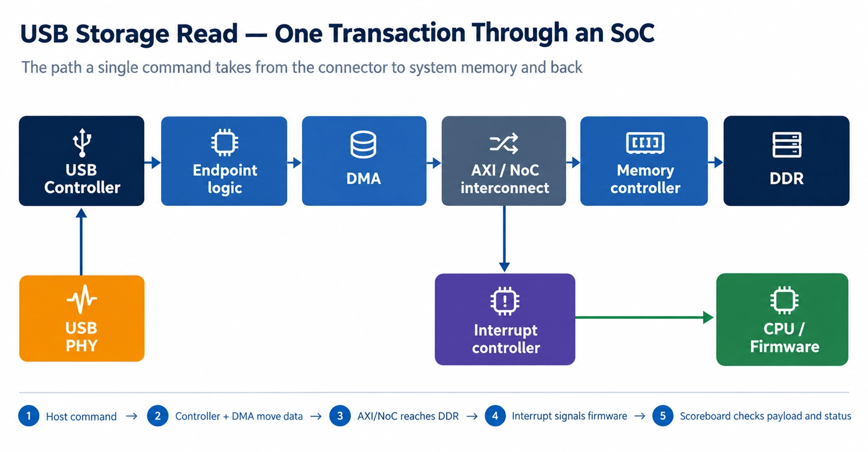
A USB storage read is a good example of how far one transaction travels: the Host sends a storage command, the USB controller receives and interprets it, data moves through the USB subsystem, DMA carries it toward system memory, internal traffic passes through the AXI or NoC interconnect, DDR stores the payload, and completion status reaches firmware through registers or an interrupt.
This is where SoC verification starts to differ from IP verification. IP-level verification asks whether the USB controller itself works correctly in isolation. SoC-level verification asks a bigger question: does USB behave correctly once it is wired into DMA, the interconnect, memory, firmware, and the rest of the system, under real traffic and real contention.
How USB Gets Verified in a Professional DV Environment
A practical USB verification effort is usually organised in layers:
- IP level — verify the USB controller block on its own.
- Subsystem level — verify USB together with the PHY, control logic, DMA, registers, and interrupts.
- SoC level — verify USB traffic as it passes through the interconnect, memory, firmware, and other system blocks.
- System level — verify real use cases such as storage, camera, docking, or charging end to end.
A typical UVM environment includes USB agents, sequencers, drivers, monitors, protocol checkers, a scoreboard, a reference model, functional coverage, and a register model. The monitor watches actual USB activity on the bus. The scoreboard compares what was observed against what the reference model expected. Assertions check rules that must hold at all times. Coverage answers a simple question: what has this environment actually exercised, and what has it missed?
A representative end-to-end test might look like this: create a USB data transfer, let the controller accept it, let DMA write it to memory, follow the AXI transactions to DDR, generate an interrupt, have firmware read the status, and let the scoreboard confirm the final payload and status match expectations.
The debug rule that saves the most time: when a test fails, do not stare at the final error message first. Find the first point where reality diverges from the expected result, then trace the transaction backward: application result, memory, AXI, DMA, USB controller, packet and link activity, until the divergence is found. Know the packet, understand the link, see the whole system, and debug the first wrong bit rather than the last visible symptom.
Frequently Asked Questions
What is USB enumeration, and why does it matter for verification?
Enumeration is the sequence a Host runs every time a device is plugged in: reset, address assignment, descriptor requests, and configuration selection, before any application data can move. It touches reset behaviour, control transfers, and descriptor parsing all at once, which makes it one of the highest-value areas to target early in a USB test plan.
Is USB Type-C the same thing as USB4 or USB 3.x?
No. Type-C is a connector and cable specification. A Type-C port can carry USB 2.0, USB 3.x, USB4, DisplayPort, or power delivery features depending on what the product actually implements and negotiates. The connector alone tells you nothing about the protocol running through it.
What are the four USB transfer types, and when is each one used?
Control handles commands and configuration, Bulk moves large reliable data such as storage traffic, Interrupt carries small periodic or event-driven data for devices like keyboards and mice, and Isochronous carries time-sensitive audio or video streams. Each one trades reliability, bandwidth, and timing differently, so a device usually mixes more than one type across its endpoints.
Why does USB Power Delivery need its own verification effort?
USB PD is a separate negotiation protocol layered on top of the physical connector, covering how a source and a sink agree on voltage, current, and role. A Type-C controller that handles PD messaging, orientation detection, and power-state control has to be checked as a connected system, since a bug in one area (role swap timing, say) can surface as a failure somewhere else entirely, such as a data-path reset.
How is USB verified differently at the SoC level compared with the IP level?
IP-level verification checks whether the USB controller behaves correctly on its own, against its own specification. SoC-level verification checks whether that same controller still behaves correctly once it is connected to DMA, the interconnect, memory, firmware, and every other block competing for the same shared resources, which is where a large share of real silicon bugs actually surface.
Why does USB4 verification take more effort than USB 3.x?
USB4 adds a transport layer that tunnels several protocols (USB data, DisplayPort, and PCI Express among them) across a single physical link. That means a USB4 environment has to verify arbitration between tunnelled protocols, link-state transitions, and end-to-end data correctness for each tunnelled traffic type, on top of everything already required for USB 3.x SuperSpeed.
Five Things to Remember
- USB is a protocol ecosystem, not just a connector.
- The Host controls bus transactions and discovers devices; devices respond according to their transfer type.
- Enumeration is how the Host learns what a device is and configures it, and it is a major functional area, not a formality.
- USB 2.0, USB 3.x, and USB4 represent distinct architectural generations, each with its own verification demands.
- Type-C, USB data generation, and USB Power Delivery are related but separate concepts, and a real testbench has to treat them that way.
Closing Thoughts
USB has lasted this long because it kept adding capability without abandoning the original idea of one connector doing the work of many. From the first Low-Speed peripherals through SuperSpeed links to USB4 tunnelling, the story is the same one repeated at a larger scale each time: more bandwidth, a smarter protocol, and deeper ties into the rest of the system.
For a verification engineer, USB is worth learning in depth precisely because it connects protocol knowledge to real SoC behaviour: packets, state machines, link management, DMA, AXI, memory, interrupts, and firmware, all in one interface. Once a single USB transaction can be followed from the connector all the way into system memory, with a clear explanation of why every stage behaved correctly, that is no longer just USB knowledge. That is SoC verification.
PQ Angels Technologies works with semiconductor product teams on exactly this kind of protocol and SoC-level verification, alongside RTL design, embedded systems, and DevOps support. Read more about the team or book a discovery call to talk through a USB verification plan for your next chip.
